ES-15
(Ver.1)
Crystal-lock Ultrasonic Motion Detector
(DC 12V) (relay contact : 2A)
[
discontinued -- now
replaced by ES-15
Version 2]
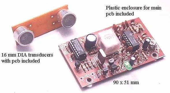
A pair of 40 KHz ultrasonic transducers detects moving
objects or human bodies up to 10 meters. A relay is energized when any object is
moving in front of the transducers. The relay will remain on as the object is
moving continuously. It de-energizes when the motion stops. The transducers are mounted on a separate pc board.
Plastic enclosure provided for the main board
Applications : Add-on motion detector for existing security
alarm system, proximity switch, visitor chime (when used with door chime), . .
ES-15 Crystal-lock Ultrasonic Motion Detector
Description of
Circuit Operation
TRANSMITTER SECTION
--- Transistor (Q3) is configured as a inverter which together with the
crystal (XTAL) generates a highly stable 3.58 MHz signal. The signal is divided
by 90 by IC2 (HEF4518) to produce a
39.77 KHz square wave. This signal is sent to the base of
transistor (Q4) which drives the transducer
(TD1). The transducer (TD1) converts the electrical signal to (inaudible)
ultrasonic wave.
RECEIVER SECTION --- The wave strikes surrounding objects and reflects back to the transducer (TD1) which converts the ultrasound to electrical signal. This weak signal is amplified 470 times by IC1A & IC1B to a useful level. If no object is moving in front of the transducers, the reflected signal has a constant frequency of 40KHz and a fixed amplitude (Fig 1). When an moving object enters the detection zone, the reflected wave takes the form as depicted in Fig.2.
The amplitude of the waveform now varies with the speed of the moving object. The outline of the varying amplitude is called the "envelop". The frequency of the "envelop" changes proportionally with the speed of the moving object. The envelop signal is extracted from the 40 KHz signal and is amplified 220 times by IC1C. The Schmidt trigger (IC1D) converts signal to square wave.. The square wave is then converted to DC voltage by the F-V converter comprising the passive components C9, D4, D5, C10 and R11. The DC voltage generated is used to drive the Darlington pair ( Q1 & Q2) which in turn energizes the miniature relay (RLY). The relay will remain energized until the object stops moving or goes outside the detection zone. As this happens, the relay is de-energized and the waveform reverts to its normal (standby) shape ( as in Fig.1).
If you have an oscilloscope ready, you can view the signal (Fig.2) at pin 8 of IC1 as you wave your hand in front of the transducers.