|
PARTS LIST
(for
0 ~ 1.999 V) |
Resistors
(1 or 2%)
Important : if you have problem
reading the color code of precision resistors, please use a digital ohm
meter to check & confirm the value of each resistor before insertion
R
1 -- 3 K
R 2 -- 3 K
R 3 -- 39 Ω
R 4 -- 470 Ω
R 5 -- 100K
R 6 -- 470K
R 7 -- 1M
R 8 -- 10 Ω
*
R 9-- 10K *
R10 -- 470 Ω
Q1 --- 2.5V precision
Voltage reference IC (# TL431)
Datasheet
(pdf)
Diode
D1 -------- 1N4007
rectifier diode
D2 & D3 -- 1N4148 switching diodes
W1 --- Multi turn
precision trimmer pot
5K (# 502)
|
14-pin DIP IC
socket (for IC1)
40-pin DIP IC socket (for IC2)
PCB connectors -- 2-pin (2.54mm
pitch)
Capacitors
C1 -- (not
required)
C2 -- 100pF ceramic cap (# 101 or 100p)
C3 -- 0.1 uF mylar cap (# 100n or 104)
C4 -- 4.7uF E.cap
C5 -- 4.7uF E.cap
C6 -- 0.47uF (# 474 or 470n)
C7 -- 0.22uF (# 224 or 220n)
C8 -- 0.01 uF (# 103 or 10n)
C9 -- 0.1 uF ceramic cap (# 104 or 100n)
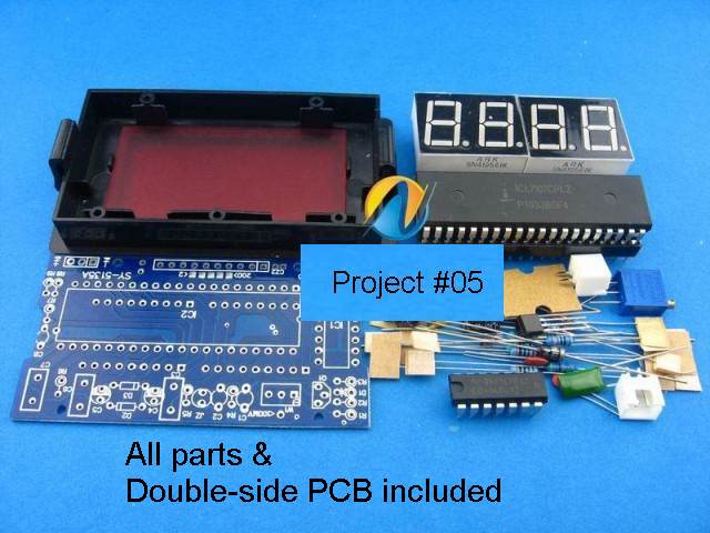
Double
side, FR4 printed circuit board
included
IC1 -- CMOS hex inverters (# 4069)
Datasheet (pdf)
IC2 --- 3
1/2
digit Panel Meter IC
(# ICL7107)
Datasheet
(pdf)
Disp 1 & 2 -- 2 pcs of double,
common anode 7-segment displays
|
|
CONSTRUCTION |
|
Please follow closely the
assembly procedure as stated below. The sequence of steps is very
important & should not be changed. The project is constructed on a
double-side
PCB .
Removing parts after
soldering is very difficult
!
Double-check the location & orientation of each component before
soldering. |
|
<STEP-1> insert & solder the
-> |
Resistors
Diodes
ceramic & mylar capacitors
electrolytic
capacitors
TL431 (Q1)
40-pin & 14-pin IC sockets
(empty sockets
without the ICs)
2-pin pcb connectors |
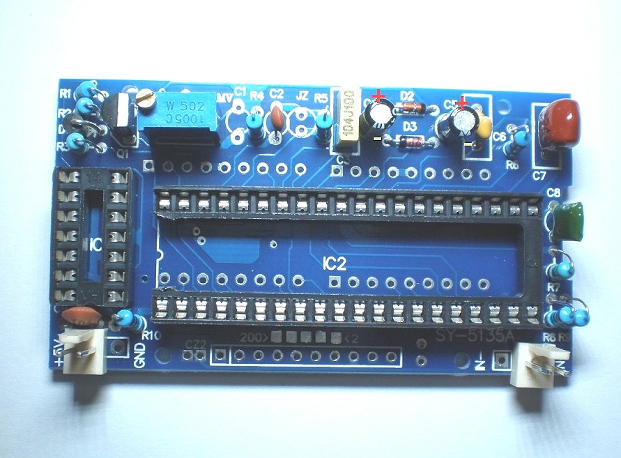 |
| Note : One end of the
40-pin IC socket has been intentionally cut to make soldering of the
displays (in step2) easier |
|
► |
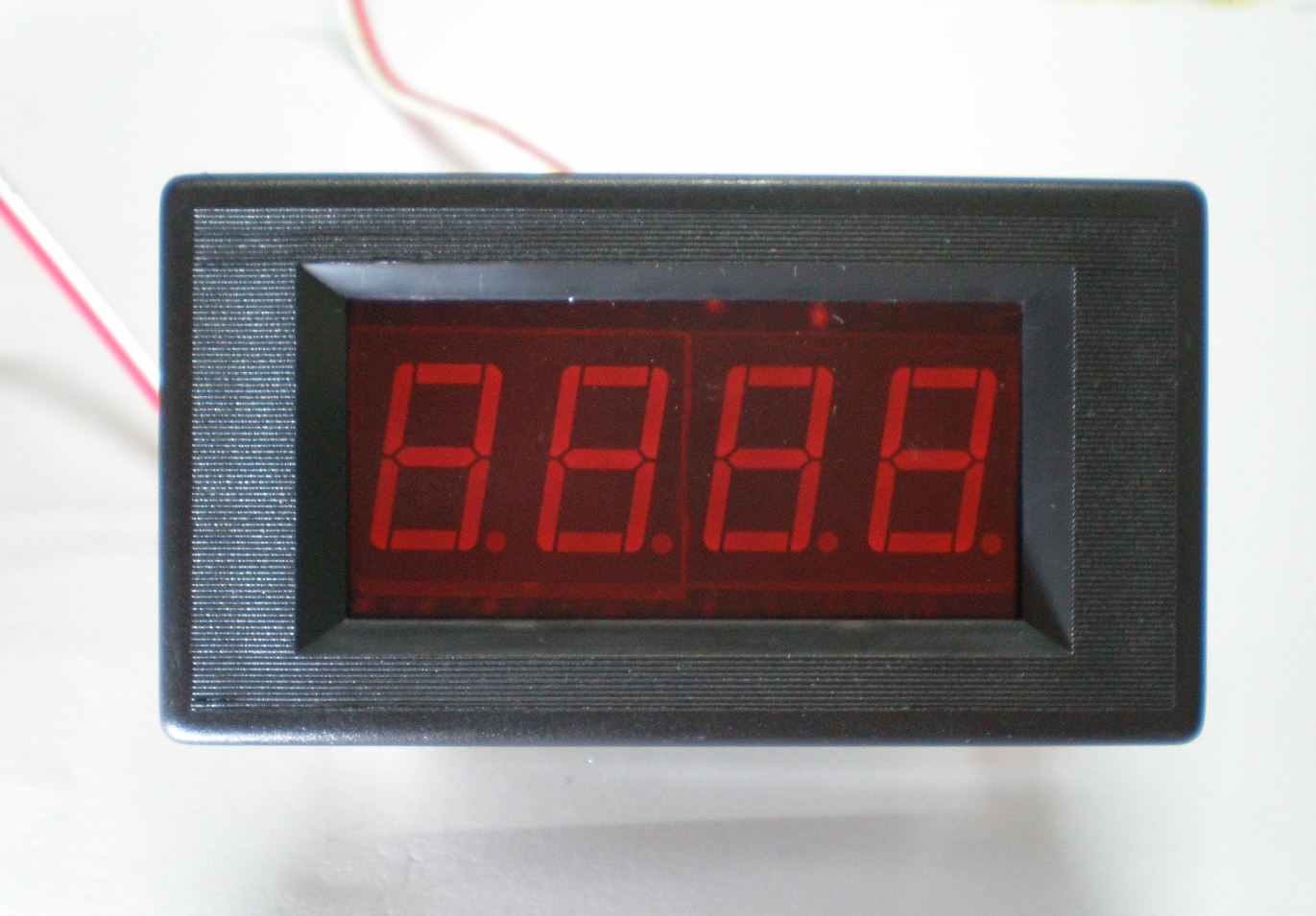
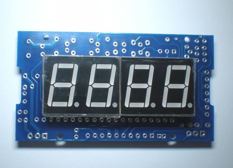
<STEP-2>
Insert & solder the 2-digit, 7-segment LED displays ( 2 pcs)
Watch for the orientation of the
displays
Please DO NOT insert the displays upside down !
 |
|
|
|
▼ |
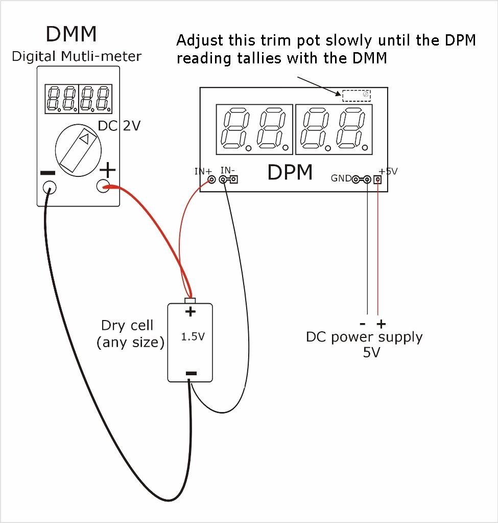
<STEP-4>
Test & Calibration
- Hook-up the test circuit (see diagram
below) & calibration the DPM as shown.
- You will need :
1) a stable 5V DC power supply to power up the DPM
2) an accurate digital voltmeter (2V F/s)
3) a 1.5V battery (any size) and
4) a small screw driver for adjusting the DPM's trim pot

Note that the actual voltage of the
battery is not important. It is merely used a temporary voltage
reference for calibration purpose. Our objective is to tune the DMP so
that it gives the same reading as the digital multimeter.
|
◄ |
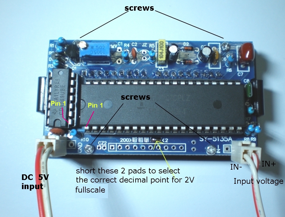
<STEP-3>
- Insert the ICs to their respective
sockets.
(ensure that the locations of pins # 1 are correctly
identified)
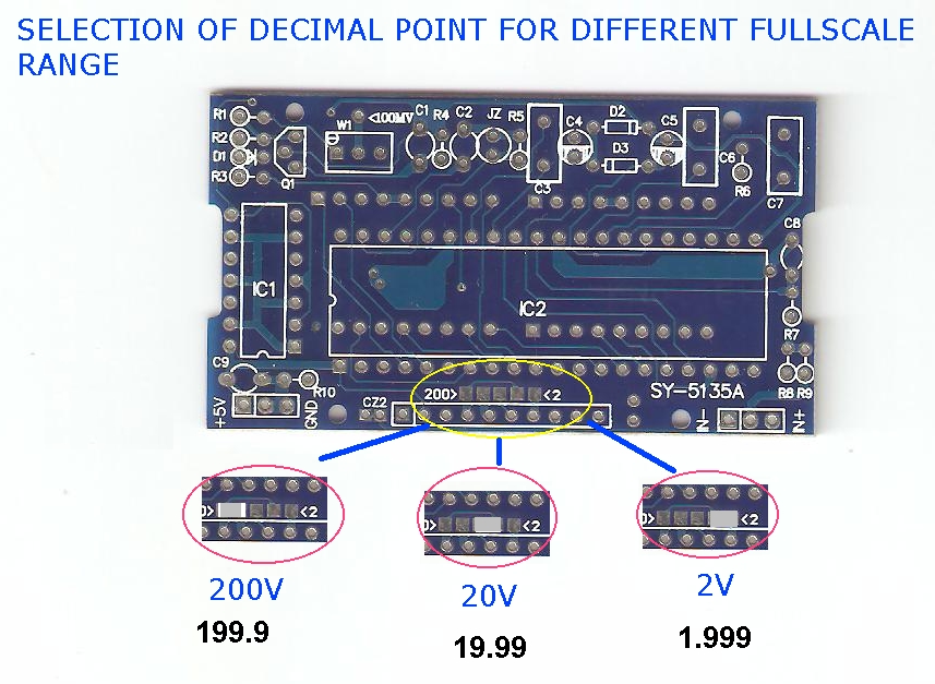
- Set the correct decimal point for
2V full-scale by shorting (with solder) the 2 rightmost pads (see
photo)
- Install the pcb on the plastic
snap-in panel mounting cover & secure it with 4 screws
- Insert the 2-pin wired connectors
(2 sets) to the pcb & proceed to the calibration step
|