|
||||||||
|
|
||||||||
|
||||||||
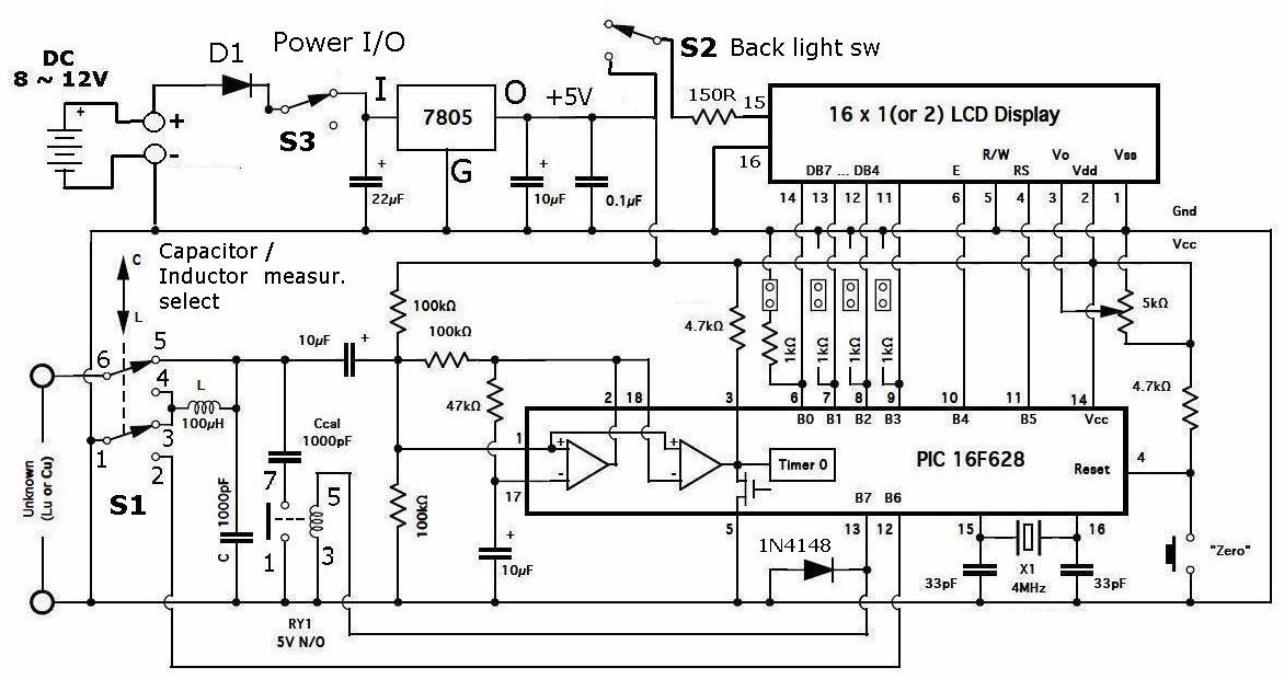
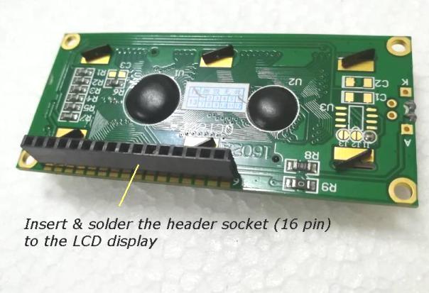
CONSTRUCTION |
||||||||
|
||||||||
TEST & CALIBRATION (needs to be done only once) |
||||||||
|
|
||||||||
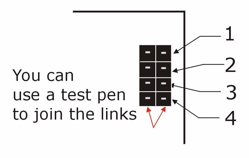
** Please refer to Phil Rice's Home Page. for a full description of calibration procedure under the title " Calibration Instructions " |
||||||||
|
HOW TO USE |
||||||||
|
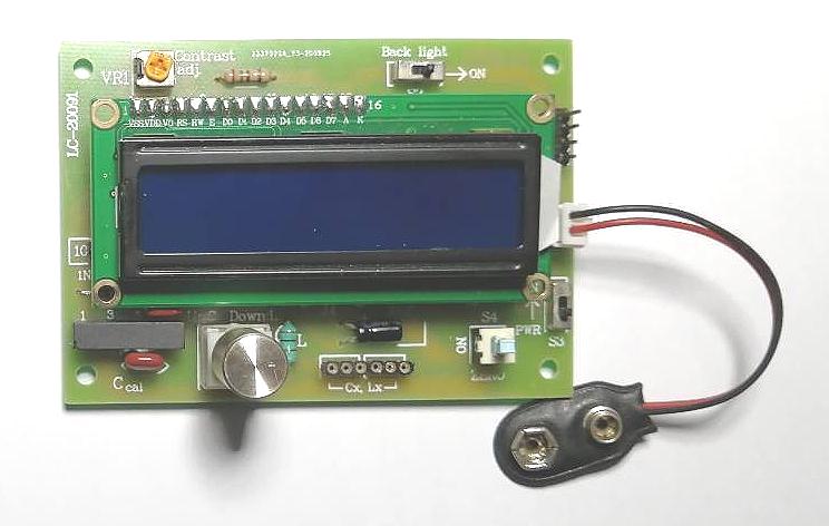
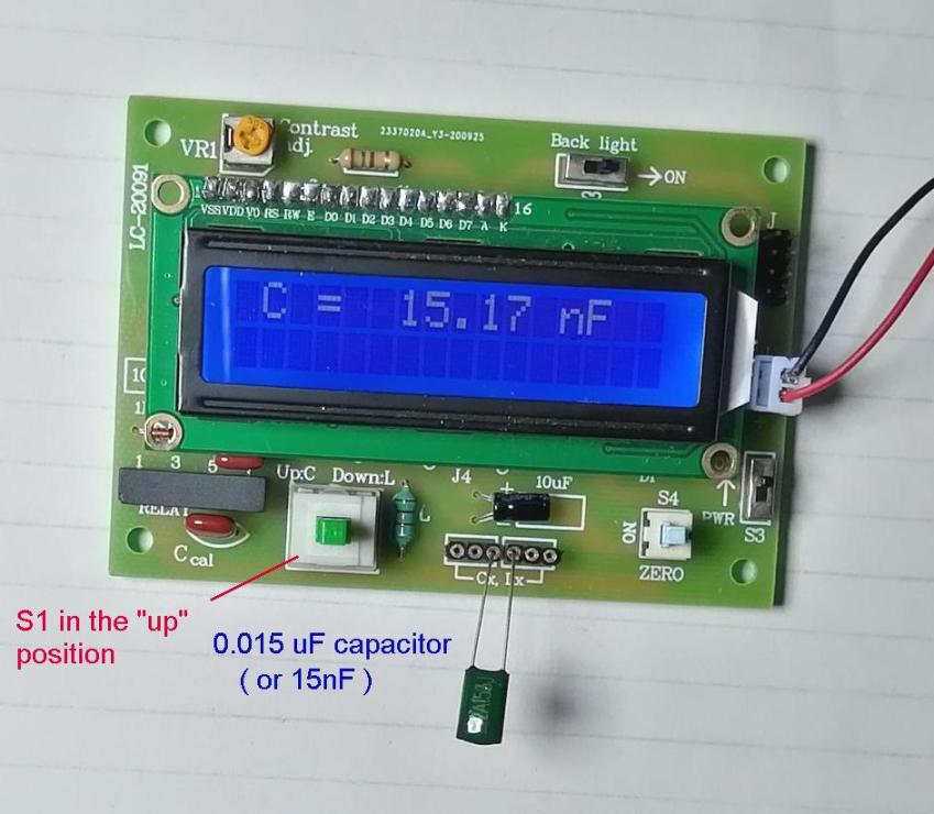
CAPACITANCE MEASUREMENT :
1 Set the mode switch (S1) to "up" position 2. Switch on the
meter (S3) & let the meter initialize (the reading may not be
zero).
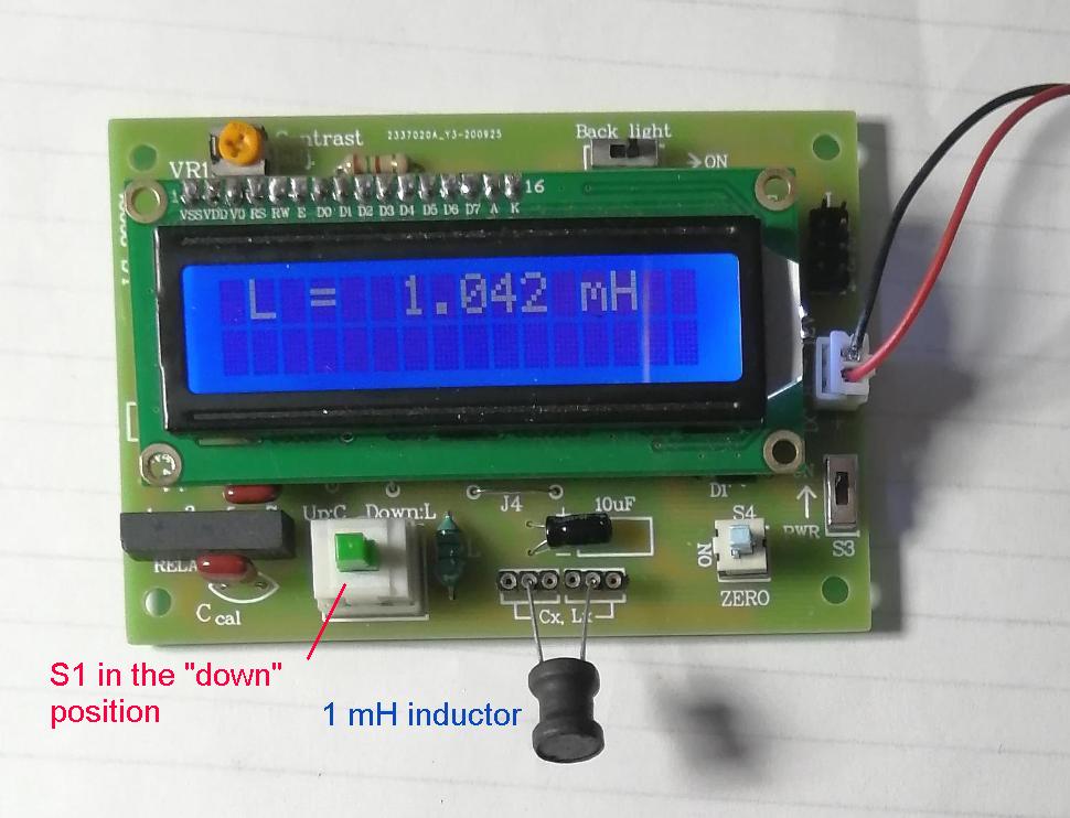
INDUCTANCE
MEASUREMENT :
1 Set the mode switch (S1) to "up" position as in the case of capacitance measurement 2. Switch on the
meter (S3) & let the meter initialize (the reading may not be
zero). 3.
Now set the mode switch (S1) to "down" position for inductance
measurement |
||||||||
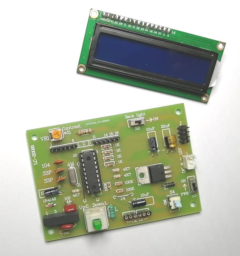
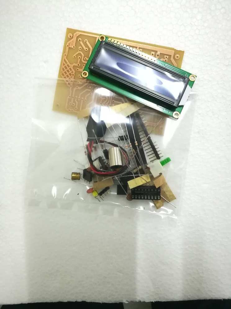
PARTS LIST |
||||||||
|

.jpg)